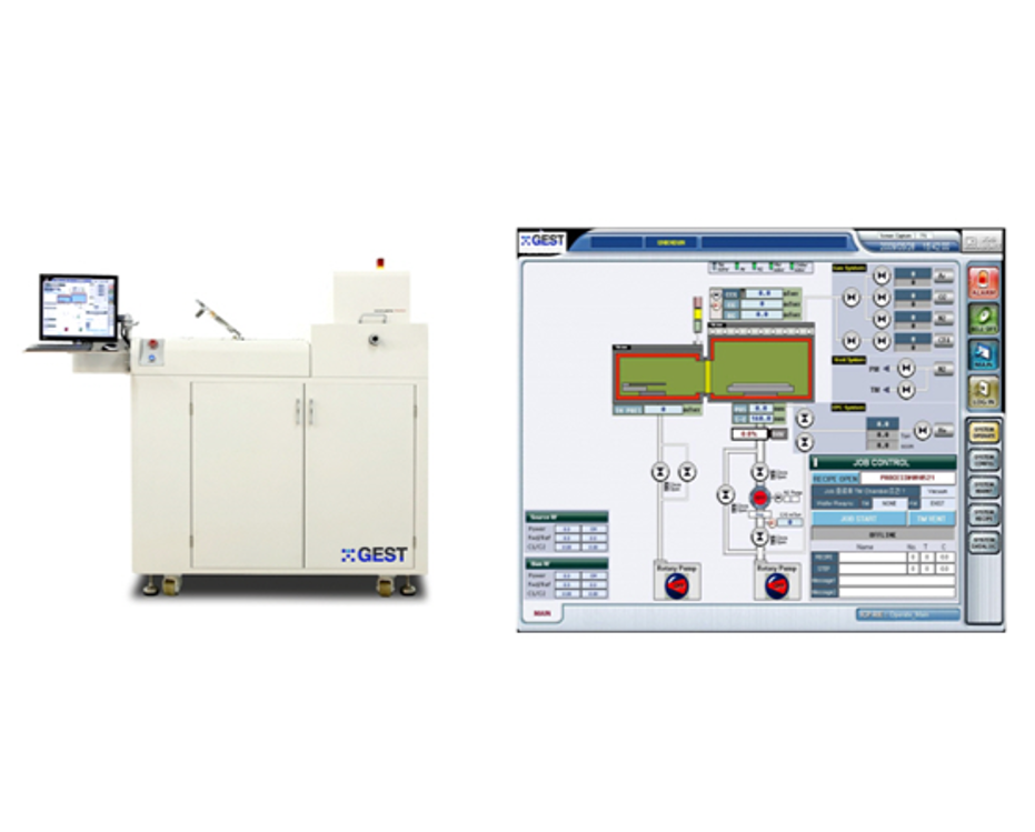
ICP_RIE Specification_1
작성자관리자
- 등록일 24-02-26
- 조회496회
본문
ICP_RIE |

| ICP_RIE Specification | |||
| 1. SYSTEM DIMENSION | |||
| - General | |||
| Dimension (mm) : 2000(W) x 1300(D) x 1650(H) | |||
| Weight : 550 kg | |||
| Color : White | |||
| 2. CHAMBER MODULE | |||
| - Process Chamber | |||
| Chamber material : Anodized aluminum (Cylinder type) | |||
| Wafer loading/unloading type : Automatic transfer operation | |||
| Port : Vacuum port, View port, Pressure gauge port | |||
| - ICP Source | |||
| Top Plasma source : Inductively coupled plasma | |||
| Water cooling or Forced-air cooling | |||
| Water cooling or Forced-air cooling | |||
| - Substrate | |||
| Wafer size :4 inch (Φ100mm) | |||
| Substrate capacity :1(single) substrate | |||
| Clamping method :Q' TZ (Ring Type) | |||
| Water cooling :Chiller (Working Temp. range 5 ~ 35℃) | |||
| He backside cooling | |||
| - Loadlock chamber unit | |||
| Chamber material :SUS304 | |||
| Wafer capacity :1(single) wafer | |||
| Automatic transfer operation | |||
| Chamber purge & vent line | |||
| Rectangular gate port (include rectangular type isolation valve) | |||
| View port | |||
| 3. VACUUM MODULE | |||
| - Vacuum Pump | |||
| Rotary pump ™ | |||
| Rotary pump (PM) | |||
| Turbo pump (PM) | |||
| Ultimate pressure : 5×10⁻⁶ Torr (PM) / 5×10⁻³ Torr ™ | |||
| - Vacuum pressure gauge (TM) | |||
| Low vacuum gauge : Convectron gauge | |||
| Pressure readout | |||
| - Pressure Gauge (PM) | |||
| High vacuum gauge : Cold cathode gauge | |||
| Low vacuum gauge : Convectron gauge | |||
| Pressure readout & cable kit | |||
| - Vacuum Pressure Control | |||
| · APC(Automatic Pressure Control) | |||
| Automatic throttle valve | |||
| Throttle valve controller | |||
| Baratron gauge : 1 Torr F.S. | |||
| - Vacuum Valve | |||
| Main valve :Pneumatic type gate valve | |||
| Fore line valve : Pneumatic type angle valve | |||
| Roughing line valve : Pneumatic type angle valve | |||
| Soft pumping valve : Pneumatic type bellows valve | |||
| - Vacuum Line | |||
| Auto vent line | |||
| SUS hard line and flexible bellows line | |||
| 4. GAS DELIVERY MODULE | |||
| - Used gases & flow control | |||
| Process gas : | Ar | MFC | (100sccm) |
| O2 | MFC | (100sccm) | |
| N2 | MFC | (100sccm) | |
| CF4 | MFC | (100sccm) | |
| He | EPC | ||
| Purge & vent : | N2 - | Metering valve | |
| 1㎛ filter for each channel | |||
| - Gas valves & gas line | |||
| It used swagelok pneumatically operated diaphragm valves, which is Air-actuated(N/C) | |||
| Metering valve for N2 purge and vent | |||
| Tubing of 316L stainless steel | |||
| All gas lines are welded by auto-welding method with VCR fitting. | |||
| 5. CONTROL MODULE | |||
| - System control | |||
| · Automatic process control by PC | |||
| Industrial PC (PENTIUM, 17” LCD monitor) | |||
| Process control software | |||
| User friendly screen & easy graphic user interface(GUI) | |||
| Recipe edit, save, download, run | |||
| Process data logging |


